가입하다 TMAX, 대리인이 되다!
가입하다 TMAX, 대리인이 되다!
Sales Manager:David
Email:David@tmaxcn.com
Wechat:18659217588
품목 번호:
TMAX-Polymer-Pack지불:
L/C, T/T, Western Union, Credit Cards, Paypal제품 원산지:
China선적항:
Xiamen Port리드타임:
5 Days자격증 :
CE, IOS, ROHS, SGS, UL Certificate보증 :
Two years limited warranty with lifetime technical support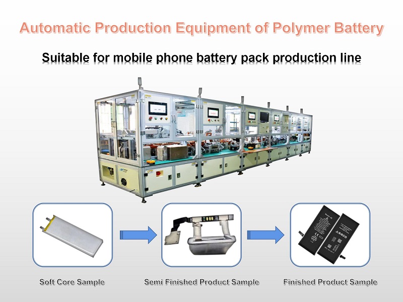
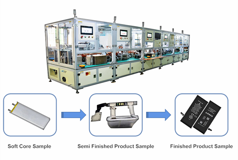
1. 장비F 기름 부음I 소개
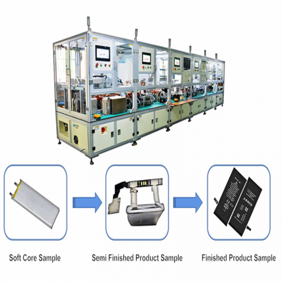
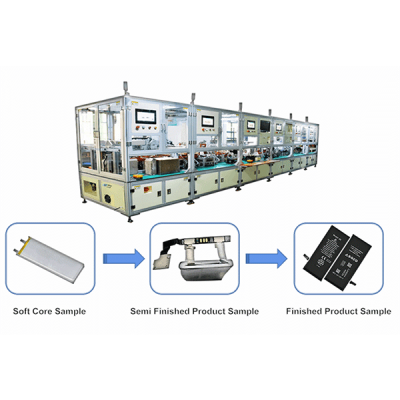
자동 생산 라인은 주로 휴대 전화 배터리 팩 생산 공정을 완료하는 데 사용됩니다.
프로세스 흐름에는 다음이 포함됩니다.
1)피 폴리머 배터리 탭 성형,
2) OCV 테스트,
3)배터리 탭 절단,
4) 여 장로,
5)D 양면 접착제 붙여넣기,
6)BMS 굽힘,
7) 에이 접착제 붙여넣기 그리고 형성,
8) 에프 완성된 배터리 테스트;
9) FPC 스폰지 접착제 붙여넣기.
공정 흐름 및 기술 요구 사항에 따라 팩 라인은 다음 5가지 장비로 연결됩니다.
(1)아 자동 급지 + 다기능m 통증;
(2) 자동 레이저 용접기;
(삼) 양면 접착 테이프 + L 자형 니켈 시트 벤딩 + 보호 플레이트 벤딩 머신;
(4) 자동 헤드 접착 기계.
 2.프로세스 흐름
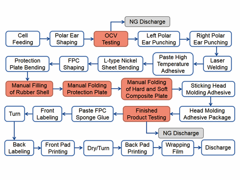
3.기술적 매개변수
1. 배터리 크기의 적용 범위(단위: mm):
길이: 40-130mm(폴 러그 길이 제외)
폭: 30-70mm
두께: 3-10mm
러그 길이: 4-20mm
2. 환경 조건:
공기 소스의 공기 압력: 0.5 ~ 0.6 MPa
전원 공급 장치 전압: 220V, 50Hz
총 전력:≤ 15kw
면적 베어링 비율:≤ 500kg/남²
주변 온도: 5º C-50ºC
습도: 50% - 90%
3. 생산 라인 효율성:≥ 900개/시간
4. 장비 가동률: > 98%
5. 제품 적격률: > 98%
6. 장비의 공급 및 방전 방향은 일관되어야하며 전기 코어의 꼬리는 장비 작동 표면을 향해야합니다.
7. 공정 적용 가능성: 동일한 공정으로 소프트 팩 배터리에 적용 가능.
8. 제품 안전 및 배터리 안전을 포함한 안전 생산 요구 사항을 충족합니다.
9. 전체 치수(조립 라인 제외):
와이어 본체: 9200(긴)*1200(폭)*1900(높이) mm
조립 라인 높이: 900mm± 50mm
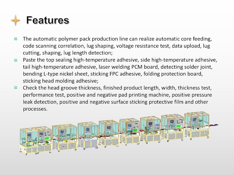
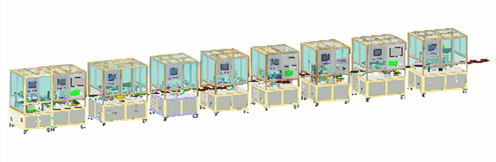
4. 전체 장비 레이아웃 및 장비 워크플로 설명
라인 바디의 전체 레이아웃:
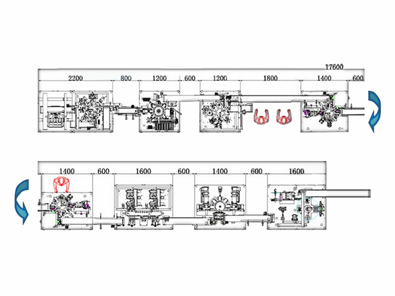
참고: 라인에는 4명이 포함되어 있으며 그 중 한 명은 레이저 기계 보호 보드를 담당합니다.
고무 쉘 설치는 2명이 담당합니다.
한 사람이 공급, 전체 라인 검사 및 테이프 등의 재료 교체를 담당합니다.
단일 장비의 기능 및 작업 요구 사항:
(1) 자동 급지 + 다기능 기계:
1) 기능적 작용
① 배터리는 공급 트레이에서 공급 기계를 통해 공급 기계의 조립 라인에 자동으로 로드되며, 포지셔닝 실린더가 배치되었습니다.
② 시프트 매니퓰레이터는 적재 기계 조립 라인에서 다기능 기계 공급 조립 라인으로 배터리를 움켜쥡니다. 배터리는 90도 회전 가능° 또는 마음대로 뒤집었다.
③ 전기 코어는 다기능 기계의 공급 조립 라인을 통해 들어갑니다. 전기 후 코어가 배치되면 공급 조작기에 의해 회전 테이블의 공급 스테이션으로 잡힙니다.
④ 회전 테이블은 시계 방향으로 회전하여 극 귀 성형을 위한 기본 극 귀 성형 스테이션에 들어갑니다.
⑤ 회전 테이블을 시계 방향으로 돌려 테스트 스테이션에 들어가 전압 내부 저항을 테스트하고 코드를 스캔하고 데이터를 업로드하십시오.
⑥ 회전 테이블은 시계 방향으로 회전하여 왼쪽 탭 절단 스테이션으로 들어가 왼쪽 탭을 절단합니다.
⑦ 회전 테이블은 시계 방향으로 회전하고 오른쪽 탭의 절단 스테이션으로 들어가 오른쪽 탭을 절단합니다.
⑧ 회전 테이블 썩음 먹었다 s 시계 방향으로; 탭 이차 성형 수술, 극귀 성형 수술을 입력하십시오.
⑨ 회전 테이블은 시계 방향으로 회전하여 배터리 방전 스테이션에 들어가 배터리를 방전하고 장비의 공급 라인으로 가져갑니다. 셀이 90도 회전합니다.° 그리고 180이 된다.°.
2) 기술 요구 사항
① 수용량 (UPH): ≥1200pcs/h
② 장비 가동률: > 98%
③ 적격 비율: > 99.5%
④ 극 러그 절단 길이의 편차 범위: ±0.2mm
⑤ 절단기 수명 ≥400000배
⑥ 전압 테스트 정확도: ±0.01% rdg. ±3dgt( 테스터의 정확도에 따라);
⑦ 내부 저항 테스트 정확도: ±0.5% rdg.±5dgt( 테스터의 정확도에 따라);
⑧ 오판율: 채널 OK 제품에서는 100%, 채널 ng 제품에서는 ≤0.3%이어야 합니다.
⑨ 셀 코드를 스캔하고 테스트 데이터를 바인딩 및 업로드합니다.
⑩ 재료는 쌓인 플라스틱 흡입 트레이에서 꺼낼 수 있습니다. 트레이와 트레이를 연결할 수 없습니다. 배터리는 회수 과정에서 손상될 수 없습니다. 재료를 가져온 후 빈 트레이는 자동으로 제거되어 스택으로 분류됩니다.
⑪ 전체 치수(조립 라인 제외):
2200(길이)*1200(폭)*1900(높이) mm.
⑫ 재료 크기:
메모:T 전기 코어 로딩 리프팅 테이블의 하중은 40kg 이하입니다.
N 에임 | 길이(mm) | 폭(mm) | 두께(mm) | R 표시 |
흡입관P 라스틱T 레이 | 270-420mm | 215-350mm | 여러 층의 스태킹 높이 ≤ 250mm | 각 패널의 전기 셀 수는 2입니다.-8 |
배터리 | 40- 140mm | 35- 80mm | 3- 8mm |
3) 키 구성
① 테스터: Lanqi BK600A, 1 세트
② 스캐닝 건: Honeywell, 1세트
(2) 레이저 용접기:
1) 기능적 작용
① 배터리는 공급 조립 라인을 통해 레이저 기계에 들어가고 공급 조작기에 의해 보조 위치로 파악되고 배터리가 90도 회전합니다.°;
② 로딩 매니퓰레이터는 보조 위치에서 턴테이블 로딩 스테이션으로 배터리를 잡고 배터리는 45도 회전합니다.°;
③ 회전 테이블은 극 귀 성형을 위한 극 귀 성형 스테이션에 들어가기 위해 시계 반대 방향으로 회전합니다.
④ 회전 테이블은 시계 반대 방향으로 회전하고 보호 플레이트를 로드하기 위해 보호 플레이트의 공급 스테이션으로 들어갑니다.
⑤ 회전 테이블은 시계 반대 방향으로 회전하고 보호 플레이트 위치 지정 스테이션으로 들어가 보호 플레이트를 배치합니다.
⑥ 회전 테이블은 시계 반대 방향으로 회전하여 레이저 용접을 위한 레이저 용접 스테이션으로 들어갑니다.
⑦ 회전 테이블은 배터리를 입력하기 위해 시계 반대 방향으로 회전합니다.
방전 스테이션에서 배터리를 방전하고 장비의 급전선으로 잡으십시오.
2) 기술 요구 사항
① 용량(UPH):≥ 1200개/시간;
② 장비 가동률: > 98%;
③ 적격 비율: > 99.5%;
④ 레이저 용접의 위치 정확도:± 0.02mm;
⑤ 전기 코어의 보호판과 전극 러그의 용접 위치와 위치 정확도를 확인하십시오.± 0.1mm;
⑥ 스폿 용접의 사전 판단 (보호판과 전기 코어의 전극 러그가 배치되었을 때 용접이 OK, NG일 때 용접하지 않고 뽑아냄);
⑦ 용접 견고성 기준: 니켈 및 니켈 재료의 인장력≥ 2kgf, 알루미늄 및 니켈 재질의 인장력≥ 0.6kgf;
⑧ 레이저 용접의 양극 및 음극 귀 에너지는 별도로 설정하고 자유롭게 전환할 수 있습니다(참고: 레이저 기계 제조업체는 이 항목에 대한 책임이 있고 와이어 본체 제조업체는 연결 트리거 등의 책임이 있습니다).
⑨ 전체 치수(조립 라인 제외):
1200(길이)*1200(폭)*1900(높이) mm.
⑩ 재료 크기:
이름 | 길이(mm) | 폭(mm) | 두께(mm) | 비고 |
보호판 | 25-80mm | FPC 처짐 5-30mm | 0.6-1.2mm |
(3) 양면 접착 테이프 + L 자형 니켈 시트 벤딩 + 보호 플레이트 벤딩 머신:
1) 기능적 작용
① 배터리는 공급 조립 라인을 통해 양면 접착 테이프 + L 자형 니켈 시트 벤딩 + 보호 플레이트 벤딩 머신에 들어갑니다. 전기 셀이 배치된 후 공급 조작기에 의해 턴테이블 로딩 스테이션으로 잡힙니다.
② 컵 입구에 양면 접착제의 접착을 완료하기 위해 접착 스테이션에 들어가기 위해 회전 테이블을 시계 반대 방향으로 돌립니다.
③ 회전 테이블은 시계 반대 방향으로 회전하고 L 자형 니켈 시트를 구부리기 위해 L 자형 니켈 시트 벤딩 스테이션으로 들어갑니다.
④ 회전 테이블은 시계 반대 방향으로 회전하고 성형 스테이션으로 들어가 L 자형 니켈 시트를 성형하여 맞춤을 보장합니다.
⑤ 회전 테이블은 시계 반대 방향으로 회전하여 FPC 성형 스테이션으로 들어가 FPC를 성형합니다.
⑥ 회전 테이블은 시계 반대 방향으로 회전하여 보호 플레이트 벤딩 스테이션에 들어가 보호 플레이트 90을 구부립니다.°
⑦ 회전 테이블은 시계 반대 방향으로 회전하고 배터리 방전 스테이션으로 들어갑니다. 배터리 방전은 매니퓰레이터에 의해 장비의 공급 조립 라인으로 직접 잡힙니다.
⑧ 수동으로 고무 쉘을 설치하고 보호판을 수동으로 접고 부드럽고 단단한 결합판을 수동으로 접는 과정을 조립 라인에 수동으로 완료 한 후 배터리가 장비로 흘러 들어갑니다.
2) 기술 요구 사항
① 용량(UPH):≥ 1000개/시간;
② 장비 가동률: > 98%;
③ 적격 비율: > 99.5%;
④ 양면 접착 실린더의 내경(mm):∅ 76;
⑤ 접착 정확도:± 0.25mm;
⑥ 굽힘 각도: 90도 이하;
⑦ 전기 코어, 보호 플레이트 및 그 구성 요소는 손상을 방지하기 위해 보호되어야 합니다.
⑧ 전체 치수(조립 라인 제외):
1200(길이)*1200(폭)*1900(높이) mm.
(4) 완전 자동 헤드 접착 기계:
1) 액션 기능
① 배터리는 공급 라인을 통해 헤드 접착 기계에 들어갑니다. 전기 셀이 배치된 후 공급 조작기에 의해 턴테이블 로딩 스테이션으로 잡힙니다.
② 회전 테이블을 시계 반대 방향으로 돌려 헤드 접착 스테이션에 들어가고 배터리 상단 표면에 성형 접착제를 붙입니다.
③ 회전 테이블을 시계 반대 방향으로 돌려서 접착제 포장 스테이션에 들어가고 배터리 뒷면의 몰딩 접착제 양쪽에 귀를 감습니다.
④ 회전 테이블은 시계 반대 방향으로 회전하여 접착제 포장 스테이션에 들어가고 배터리 뒷면에 접착제를 형성하는 헤드의 상단을 감습니다.
⑤ 회전 테이블은 시계 반대 방향으로 회전하여 배터리 방전 스테이션으로 들어가 배터리를 방전하고 장비의 급전선으로 잡습니다.
2) 기술적인 매개변수
① 용량(UPH):≥ 1100개/시간;
② 장비 가동률: > 98%;
③ 적격 비율: > 99.5%;
④ 양면 접착 실린더의 내경(mm):∅ 76;
⑤ 접착 정확도:± 0.25mm;
⑥ 전체 치수(조립 라인 제외):
1400(길이)*1200(폭)*1900(높이) mm.
5. 장비에 대한 일반 요구 사항
(1) 일반 사용 요건
1) 각 스테이션 장비는 각 모듈의 요구 사항에 따라 독립 작동 또는 바인딩 작동을 선택하고 데이터를 저장할 수 있습니다.
2) Tooling Fixture는 교체가 가능하며 다른 모델의 제품에도 적용 가능합니다.
3) 쉽게 마모되는 부품은 별도 교체가 가능해야 합니다.
4) 장비의 활동성과 강도가 높은 스테이션의 나사는 미끄럼방지 처리를 하여야 하며 베이클라이트 및 기타 부품의 나사구멍에는 치과용 교정기를 설치하여야 한다.
5) 전도체의 낙하, 찌그러짐, 긁힘, 용접 등 전선심에 손상을 줄 수 있는 부분은 피하거나 보호한다.
6) 전체 장비의 정전기 처리는 다음을 충족해야 합니다.
회사의 요구 사항 및 보호 플레이트의 접촉 부분은 정전기 방지 재료로 만들어집니다.
7) 각 장비는 조명시설을 별도로 구비하여야 하며, 에너지 절약형 램프가 필요하다.
8) 제품 보호 및 품질 관리:
① 기존 수동 라인 운영 요구 사항보다 낮지 않습니다(자세한 내용은 제품 공정 흐름도 참조).
② 작동 프로세스는 배터리 바코드가 카드 클로징을 실현하기 위해 바인딩되어 처리 누락 및 결함 제품 유출을 방지해야 합니다.
(2) 기계적 안전 요건
1) 국가 안전 표준 및 국가 안전 보건 규정을 준수합니다.
2) 장비에는 보호망, 광전 보호, 보호 격자 및 기타 보호 장치와 같은 우수하고 포괄적인 안전 보호 조치가 제공되어야 합니다. 장비의 회전 부분, 위험 부분 및 위험 부분에는 보호 장치가 제공되어야 합니다.
3) 보호 장치 및 기타 시설은 작업자가 작업 위험 영역에 진입하는 것을 방지하거나 작업자가 실수로 위험 영역에 들어갈 때 장비가 해당 보호 조치를 감지하여 작업자에게 부상을 입힐 가능성이 낮은 보호 즉 보호 장치는 장비 제어 시스템과의 연결 및 연동을 실현해야 합니다.
4) 자주 조정 및 유지 보수되는 가동 부품 및 구성 요소에는 가동 보호 덮개가 장착되어야 합니다. 필요한 경우 보호 장치(보호 덮개, 보호 도어 등을 포함)를 닫지 않고 가동부를 시동할 수 없도록 연동 장치를 설치해야 합니다. 보호 장치(보호 커버, 보호 도어 등 포함)가 열리면 장비는 즉시 자동으로 정지합니다.
5) 장비의 전송, 동작, 방사 및 기타 부분에는 우수한 화면 보호 장치가 있어야 합니다.
6) 핸들, 핸드 휠 및 당김 막대와 같은 장비의 작동 메커니즘은 편리한 작동, 안전 및 노동 절약, 명확하고 완전하고 확고하고 신뢰할 수있는 표시로 설정되어야합니다.
(3) 전기 안전 요구 사항
1) 제어 시스템은 비정상적인 경우 장비의 에너지 공급이 위험을 일으키지 않고 장비 자체가 손상되거나 인명을 다치게하지 않도록 할 수 있습니다.
2) 제어 시스템은 인화성, 폭발성, 고온, 다습 및 부식성이 높은 곳에서 멀리 떨어져야 합니다. 불가피한 경우 필요한 차폐 조치를 설정하고 제어 캐비닛은 열 방출 조건이 양호해야 합니다. 제어 라인은 라인이 고장나거나 손상된 경우에도 피해를 입히지 않도록 해야 합니다.
3) 제어 시스템은 조작자가 조작하고 관찰하기에 편리한 위치에 배치되어야 합니다. 장비에는 특정 조건에 따라 필요한 비상 정지 버튼이 장착되어 있습니다. 비상 정지 장치는 자동 잠금이어야 하며 작동 색상은 빨간색입니다. 배경색이 있는 경우 배경색은 검정색으로 한다. 버튼 조작 스위치의 조작부는 팜푸시형 또는 머쉬룸 헤드형으로 한다.
4) 장비의 전기 제어 시스템: 과부하 보호 및 단락 보호 기능 포함.
5) 검사, 조정 및 유지 보수 중에 위험 영역을 관찰해야 하는 생산 장비 또는 위험 영역으로 확장해야 하는 인체의 일부가 오작동을 방지해야 합니다. 장비가 우발적인 시작으로 인해 개인의 안전을 위협할 수 있는 경우 우발적인 시작을 방지하기 위해 필수 안전 보호 장치를 구성해야 합니다.
6) 실수로 에너지를 차단했다가 다시 켜는 경우 장비는 위험한 작동을 피할 수 있어야 합니다.
7) 3상 5선식 전원 공급 장치 시스템을 채택하고 장비 외피에 대해 보호 중성선 연결 조치를 취합니다.
8) 장비 작동 중 구성 요소에 장애가 발생하거나
손상되면 장비 자체에 해당 보호 조치가 있으므로 장비 자체에 더 큰 손상을 입히거나 작업자에게 해를 끼칠 수 없습니다. 보호 조치는 주로 다음을 포함합니다: 동작 실행 시간 보호: 동작의 실제 실행 시간이 정상 값을 초과할 때 경보를 울립니다. 오작동 보호: 파이프라인의 느슨한 밀봉 및 압력 완화로 인해 작동하지 않아야 하는 부품이 작동할 때 경보가 발생합니다.
9) 분전반 콘센트 주변에 전선마모 방지대책이 있고 전원선 중간에 커넥터가 없다.
6. 중요 부품의 브랜드 및 포장 목록
(1) 중요 부품 브랜드:
아니요. | 표준 부품 범주 | 기능 및 브랜드 제한 설명 |
1 | 액자 | 표면 페인트 베이킹 처리 |
2 | 빅보드 | 표면은 20mm의 두께로 전기도금되어야 합니다. |
3 | 가공 부품 | 알루미늄 부품의 샌드 블라스팅 및 산화 처리 및 철 부품의 전기 도금 처리 |
4 | 사람 기계 | 바이알론 한정 브랜드 |
5 | PLC | Omron은 3년 보증을 제공하며 10% 포트를 보유합니다. |
6 | 전원 공급 장치 | Omron, Delta, Mingwei 및 기타 스위칭 전원 공급 장치 |
7 | 감지기 | 파나소닉, 컨스, 옴론 |
8 | 전기 제어 액세서리 | 배선 바 및 기타 전기 부품은 국내 고품질 브랜드 이상이어야 합니다. |
9 | 접촉기 | 슈나이더, 옴론 |
10 | 단추 | 슈나이더, 옴론 |
11 | 일반 모터 | 신타이좡 |
12 | 스테퍼 모터 | 레예스 |
13 | 서보 모터 | 파나소닉, 후지 |
14 | I/O 보드 | 레사이,니,구가오 |
15 | 일반 실린더 | SMC 야데케 |
16 | 로드리스 실린더 | SMC 야데케 |
17 | 솔레노이드 벨브 | 야데케 |
18 | 가스 소스 처리 조합 | 야데케 |
19 | 베어링 또는 선형 베어링 | Mismi, NSK, THK 및 기타 브랜드 |
20 | 가이드 | 상하이 은행, THK 및 기타 브랜드 |
21 | 선형 모듈 | 상하이 실버, Mismi 및 기타 브랜드 |
22 | 구조 표준 부품 | 상하이 실버, Mismi 및 기타 브랜드 |
23 | IPC | 옌샹 |
24 | 감시 장치 | 필립스 |
(2) 포장 목록
아니요. | 이름 | 수량 | 비고 |
1 | 포장 목록 | 1부 | |
2 | 적합성 인증서 | 1부 | |
3 | 사용 설명서 | 2부 | |
4 | 취약 부품의 가공 도면 | 1부 | |
5 | 전기 개략도 | 2부 | 전자 파일 |
6 | IO 연결의 개략도 | 2부 | |
7 | 장비 유지보수 매뉴얼 | 1부 | |
8 | 취약 부품 목록 | 1부 | 전자 파일 |


1 표준 수출 패키지: 내부 충돌 방지, 외부 수출 나무 상자 포장.
2 가장 적합한 방법을 찾기 위해 고객의 요구 사항에 따라 급행, 항공, 해상 운송.
3 배송 과정에서 발생한 파손에 대한 책임은 귀하에게 무료로 제공됩니다.

영업 관리자: 안드레아 이메일: Andrea@tmaxlaboratory.com 위챗: 18250801164
영업 관리자: 안드레아 이메일: Andrea@tmaxlaboratory.com 위챗: 18250801164
영업 관리자: 안드레아 이메일: Andrea@tmaxlaboratory.com 위챗: 18250801164
영업 관리자: 안드레아 이메일: Andrea@tmaxlaboratory.com 위챗: 18250801164
영업 관리자: 안드레아 이메일: Andrea@tmaxlaboratory.com 위챗: 18250801164
영업 관리자: 안드레아 이메일: Andrea@tmaxlaboratory.com 위챗: 18250801164
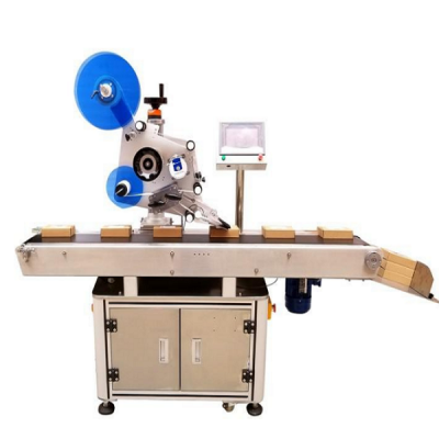
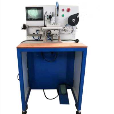
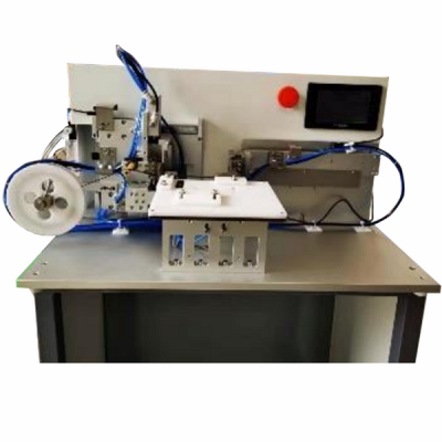
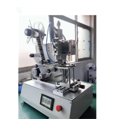
Automatic Production Equipment of Polymer Battery for Mobile Phone Battery Pack Production Line 1.Equipment Function Introduction The automatic production line is mainly used to complete the mobile phone battery pack production process. The process flow includes: 1)Polymer battery tab shaping , 2)OCV test, 3)Battery tab cutting, 4)Welding, 5)Double-sided adhesive pasting, 6)BMS bending, 7)Adhesive pasting and forming, 8)Finished battery testing; 9)FPC sponge adhesive pasting. According to the process flow and technical requirements, the pack line is connected by the following 5 equipment: (1)Automatic feeding + multifunctional machine; (2)Automatic laser welding machine; (3)Double sided adhesive tape + L-shaped nickel sheet bending + protective plate bending machine; (4)Automatic head adhesive machine. 2.Process Flow 3.Technical Parameters 1. Applicable Range of Battery Size (unit: mm): Length: 40-130mm (Excluding pole lug length) Width: 30-70mm Thickness: 3-10mm Lug length: 4-20mm 2. Environmental Conditions: Air Pressure of Air Source: 0.5 ~ 0.6 MPa Power Supply Voltage: 220V, 50Hz Total Power: ≤15kw Area Bearing Ratio: ≤500kg / M² Ambient Temperature: 5ºC-50ºC Humidity: 50% - 90% 3. Production Line Efficiency: ≥900pcs / h 4. Equipment Utilization Rate: > 98% 5. Product Qualification Rate: > 98% 6. The feeding and discharging directions of the equipment shall be consistent, and the tail of the electric core shall face the equipment operation surface. 7. Process Applicability: Applicable to soft pack batteries with the same process. 8. Meet safety production requirements, including product safety and battery safety. 9. Overall Dimension (Excluding assembly line): Wire body: 9200 (Long)*1200 (Width)*1900 (Height) mm Assembly Line Height: 900mm±50mm 4.Overall Equipment Layout and Equipment Workflow Description Overall Layout of Line Body: Note: the line includes 4 persons, one of whom is responsible for the laser machine protection board; 2 persons are responsible for installing the rubber shell; One person is responsible for feeding, inspecting the whole line and replacing materials such as tape. Function and Action Requirements of Single Equipment: (1)Automatic Feeding + Multifunction Machine: 1) Functional Action ① The battery is automatically loaded from the feeding tray to the assembly line of the feeding machine through the feeding machine, and the positioning cylinder is positioned; ② The shift manipulator grabs the battery from the loading machine assembly line to the multi-function machine feeding assembly line. The battery can be rotated by 90°or turned over at will; ③ The electric core enters through the feeding assembly line of the multi-function machine. After the electric core is positioned, it is grabbed to the feeding station of the rotary table by the feeding manipulator; ④ The rotary table rotates clockwise to enter the primary pole ear shaping station for pole ear shaping; ⑤ Rotate the rotary table clockwise to enter the test station, test the voltage internal resistance, scan the code and upload the data; ⑥ The rotary table rotates clockwise to enter the left tab cutting station to cut the left tab; ⑦ The rotary table rotates clockwise and enters the cutting station of the right tab to cut the right tab; ⑧ The rotary table rotates clockwise; Enter tab secondary plastic surgery, polar ear plastic surgery; ⑨ The rotary table rotates clockwise to enter the battery discharge station, discharge the battery, and grab it to the feeding line of the equipment; The cell rotates 90°and then turns 180°. 2) Technical Requirements ① Capacity (UPH): ≥1200pcs / h ② Equipment utilization rate: > 98% ③ Qualified rate: > 99.5% ④ Deviation range of pole lug cutting length: ±0.2mm ⑤ Cutter life ≥400000 times ⑥ Voltage test accuracy:±0.01% rdg. ±3dgt(According to the accuracy of the tester); ⑦ Internal resistance test accuracy:±0.5% rdg.±5dgt(According to the accuracy of the tester); ⑧ Misjudgment rate: it must be 100% in channel OK products and≤0.3% in channel ng products; ⑨ Scan the code of the cell, bind and upload the test data; ⑩ The material can be taken from the stacked plastic suction tray. The tray cannot be connected with the tray. The battery cannot be damaged during the reclaiming process. The empty tray after taking the material will be removed automatically and sorted into a stack; ⑪ Overall dimension (excluding assembly line): 2200 (Length)*1200 (Width)*1900 (Height) mm. ⑫ Material size: Note: The load of electric core loading lifting table is less than or equal to 40kg. Name Length (mm) Width (mm) Thickness (mm) Remarks Suction Plastic Tray 270-420 mm 215-350 mm Stacking height of multiple layers ≤ 250mm The number of electric cells in each panel is 2-8 Battery 40-140mm 35-80mm 3-8mm 3) Key Configuration ① Tester: Lanqi BK600A, 1 set ② Scanning gun: Honeywell, 1 set (2) Laser Welding Machine: 1) Functional Action ① The battery enters the laser machine through the feeding assembly line, is grasped by the feeding manipulator to the secondary positioning, and the battery rotates 90°; ② The loading manipulator grabs the battery from the secondary positioning to the turntable loading station, and the battery rotates 45°; ③ The rotary table rotates counterclockwise to enter the pole ear shaping station for pole ear shaping; ④ The rotary table rotates counterclockwise and enters the feeding station of the protection plate to load the protection plate; ⑤ The rotary table rotates counterclockwise and enters the protection plate positioning station to position the protection plate; ⑥ The rotary table rotates counterclockwise to enter the laser welding station for laser welding; ⑦ The rotary table rotates counterclockwise to enter the battery discharge station, discharge the battery, and grab it to the feeding line of the equipment. 2) Technical Requirements ① Capacity (UPH): ≥1200pcs / h; ② Equipment utilization rate: > 98%; ③ Qualified rate: > 99.5%; ④ Position accuracy of laser welding: ±0.02mm; ⑤ Check the welding position of the protective plate and the electrode lug of the electric core, and the position accuracy: ±0.1mm; ⑥ Pre judgment of spot welding (weld when the protective plate and the electrode lug of the electric core are placed OK, and pick them out without welding when NG); ⑦ Welding firmness standard: tensile force of nickel and nickel materials≥2kgf, tensile force of aluminum and nickel materials≥0.6kgf; ⑧ The positive and negative ear energy of laser welding can be set separately and switched freely (Note: the laser machine manufacturer is responsible for this item, and the wire body manufacturer is responsible for triggering the connection, etc.); ⑨ Overall dimension (excluding assembly line): 1200 (Length)*1200 (Width)*1900 (Height) mm. ⑩ Material size: Name Length (mm) Width (mm) Thickness (mm) Remarks Protective Plate 25-80 mm FPC sagging 5-30 mm 0.6-1.2mm (3)Double Sided Adhesive Tape + L-shaped Nickel Sheet Bending + Protective Plate Bending Machine: 1) Functional Action ① The battery enters the double-sided adhesive tape + L-shaped nickel sheet bending + protective plate bending machine through the feeding assembly line. After the electric cell is positioned, it is grabbed to the turntable loading station by the feeding manipulator; ② Rotate the rotary table counterclockwise to enter the gluing station to complete the gluing of double-sided adhesive at the cup mouth; ③ The rotary table rotates counterclockwise and enters the L-shaped nickel sheet bending station to bend the L-shaped nickel sheet; ④ The rotary table rotates counterclockwise and enters the shaping station to shape the L-shaped nickel sheet to ensure the fit; ⑤ The rotary table rotates counterclockwise to enter the FPC shaping station to shape the FPC; ⑥ The rotary table rotates counterclockwise to enter the protective plate bending station and bend the protective plate 90 ° ⑦ The rotary table rotates counterclockwise and enters the battery discharge station. The battery discharge is directly grabbed by the manipulator to the feeding assembly line of the equipment; ⑧ After manually completing the processes of manually installing rubber shell, manually folding protective plate and manually folding soft and hard combination plate on the assembly line, the battery flows into the equipment. 2) Technical Requirements ① Capacity (UPH): ≥1000pcs / h; ② Equipment utilization rate: > 98%; ③ Qualified rate: > 99.5%; ④ Inner diameter of double-sided adhesive cylinder (mm):∅76; ⑤ Gluing accuracy: ±0.25mm; ⑥ Bending angle: less than or equal to 90; ⑦ The electric core, protective plate and its components shall be protected to prevent damage; ⑧ Overall dimension (excluding assembly line): 1200 (Length)*1200 (Width)*1900 (Height) mm. (4) Full Automatic Head Gluing Machine: 1) Action Function ① The battery enters the head gluing machine through the feeding line. After the electric cell is positioned, it is grabbed to the turntable loading station by the feeding manipulator; ② Rotate the rotary table counterclockwise to enter the head gluing station and stick the forming glue on the upper surface of the battery; ③ Rotate the rotary table counterclockwise to enter the glue wrapping station and wrap the ears on both sides of the molding glue on the back of the battery; ④ The rotary table rotates counterclockwise to enter the glue wrapping station and wrap the top of the head forming glue to the back of the battery; ⑤ The rotary table rotates counterclockwise to enter the battery discharge station, discharge the battery, and grab it to the feeding line of the equipment. 2) Technical Parameters ① Capacity (UPH): ≥1100pcs / h; ② Equipment utilization rate: > 98%; ③ Qualified rate: > 99.5%; ④ Inner diameter of double-sided adhesive cylinder (mm): ∅76; ⑤ Gluing accuracy: ± 0.25mm; ⑥ Overall dimension (excluding assembly line): 1400 (Length)*1200 (Width)*1900 (Height) mm. 5.General Requirements for Equipment (1) General Use Requirements 1) Each station equipment can select independent operation or binding operation and save data according to the requirements of each module. 2) The tooling fixture can be replaced and is applicable to other models of products. 3) Easily worn parts must be replaceable separately. 4) Anti skid treatment must be carried out for the screws in the stations with high equipment activity and strength, and dental braces shall be installed on the screw holes on bakelite and other parts. 5) Avoid or protect the parts that can damage the electric core, such as falling, crushing, scratching, welding, etc. 6) The electrostatic treatment of the whole equipment shall meet the requirements of the company, and the contact parts of the protective plate shall be made of anti-static materials. 7) Each equipment shall be equipped with lighting facilities separately, and energy-saving lamps are required. 8) Product protection and quality control: ① Not lower than the requirements of existing manual line operation (see product process flow chart for details). ② The operation process requires that the battery bar code is bound to realize card closing to avoid missing processing and outflow of defective products. (2) Mechanical Safety Requirements 1) Comply with national safety standards and national safety and health regulations. 2) The equipment shall be provided with good and comprehensive safety protection measures, such as protective net, photoelectric protection, protective grating and other protective devices. The rotating parts, dangerous parts and dangerous parts on the equipment shall be provided with protective devices. 3) Protective devices and other facilities shall prevent operators from entering the operation dangerous area, or when personnel enter the dangerous area by mistake, the equipment can perceive the corresponding protective action, which is unlikely to cause injury to personnel, that is, the protective devices shall realize linkage and interlock with the equipment control system. 4) Movable parts and components that are frequently adjusted and maintained shall be equipped with movable protective covers. If necessary, interlocking device shall be installed to ensure that movable parts cannot be started without closing the protective device (including protective cover, protective door, etc.); Once the protective device (including protective cover, protective door, etc.) is opened, the equipment shall stop automatically immediately. 5) The transmission, action, radiation and other parts of the equipment shall have good screen protection devices. 6) The operating mechanism of the equipment, such as handle, hand wheel and pull rod, shall be set with convenient operation, safety and labor saving, clear, complete, firm and reliable marks. (3) Electrical Safety Requirements 1) The control system can ensure that the energy supply of the equipment will not cause danger in case of abnormality, and the equipment itself will not be damaged or hurt personnel. 2) The control system shall be far away from flammable, explosive, high temperature, high humidity and high corrosion areas. If it is unavoidable, necessary shielding measures shall be set, and the control cabinet shall have good heat dissipation conditions. The control line shall ensure that it will not cause harm even if the line fails or is damaged. 3) The control system shall be placed at the position convenient for operation and observation by the operator. The equipment is equipped with necessary emergency stop buttons according to specific conditions. The emergency stop mechanism must be self-locking, and its operation color is red. If there is a background color, the background color shall be black. The operating parts of button operated switch shall be palm push type or mushroom head type. 4) Electrical control system of equipment: with overload protection and short circuit protection functions. 5) During inspection, adjustment and maintenance, the production equipment that needs to observe the dangerous area or parts of the human body need to extend into the dangerous area must be prevented from misstartup. When the equipment may endanger personal safety due to accidental start, mandatory safety protection devices must be configured to prevent accidental start. 6) When the energy is cut off accidentally and then switched on again, the equipment must be able to avoid dangerous operation. 7) The three-phase five wire power supply system is adopted, and the protective neutral connection measures are adopted for the equipment shell. 8) During the operation of the equipment, when a component fails or is damaged, the equipment itself has corresponding protective measures, which can not cause greater damage to the equipment itself or harm the operator. Protection measures mainly include: action running time protection: when the actual running time of an action exceeds the normal value, it will give an alarm; Misoperation protection: due to the lax sealing and pressure relief of the pipeline, there shall be an alarm when the parts that should not act act act. 9) There are measures to prevent wire wear around the outlet of the distribution cabinet, and there is no connector in the middle of the power line. 6.Brand and Packing List of Important Parts (1) Brands of Important Parts: NO. Standard Part Category Description of Function and Brand Restrictions 1 Frame Surface paint baking treatment 2 Big Board The surface shall be electroplated with a thickness of 20mm 3 Machined Parts Sand blasting and oxidation treatment for aluminum parts and electroplating treatment for iron parts 4 Man-Machine Brand limited to vialon 5 PLC Omron has a three-year warranty and reserves 10% ports 6 Power Supply Omron, Delta, Mingwei and other switching power supplies 7 Sensor Panasonic, Kearns, Omron 8 Electric Control Accessories Wiring bar and other electrical parts shall be at least domestic high-quality brands 9 Contactor Schneider, Omron 10 Button Schneider, Omron 11 Ordinary Motor Xintaichuang 12 Stepper Motor Reyes 13 Servo Motor Panasonic, Fuji 14 I / O Board Lesai, Ni, Gugao 15 Ordinary Cylinder Yadeke, SMC 16 Rodless Cylinder Yadeke, SMC 17 Solenoid Valve Yadeke 18 Gas Source Treatment Combination Yadeke 19 Bearing or Linear Bearing Mismi, NSK, THK and other brands 20 Guide Shanghai Bank, THK and other brands 21 Linear Module Shanghai silver, Mismi and other brands 22 Structural Standard Parts Shanghai silver, Mismi and other brands 23 IPC Yanxiang 24 Monitor Philips (2) Packing List NO. Name Quantity Remarks 1 Packing List 1 copy 2 Certificate of Conformity 1 copy 3 Operation Manual 2 copies 4 Machining Drawing of Vulnerable Parts 1 copy 5 Electrical Schematic Diagram 2 copies Electronic file 6 Schematic Diagram of IO Connection 2 copies 7 Equipment Maintenance Manual 1 copy 8 List of Vulnerable Parts 1 copy Electronic file 1. We supply machines with battery technology support. 2. We supply full set of lithium battery equipment for lab research, pilot scale research and production line. 1 Standard exported package: Internal anticollision protection, external export wooden box packaging. 2 Shipping by express, by air, by sea according to customers' requirements to find the most suitable way. 3 Responsible for the damage during the shipping process, will change the damage part for you for free.
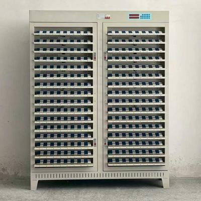
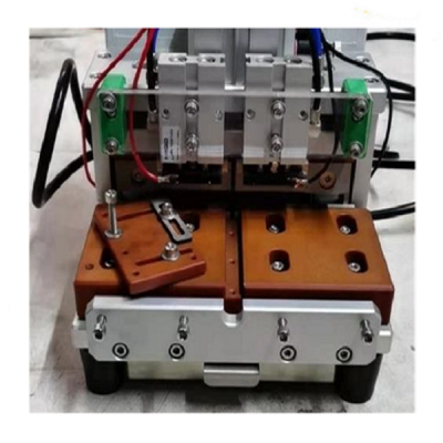
5V 10A 256 Channel Grading Machine for Pouch Cell I. Equipment Configuration List No. Category Product Name Model Quantity Remark 1 Cell Grading Equipment Pouch Cell Grading Machine TMAX-XL6512LK-5V6A 1 set 256CH5V10A 2 Accessories Communication Accessories Communication cables / RJ45 plugs, etc. Several Suitable for on-site connection II. Equipment Scope and Function 1) Equipment Application Scope: Mainly used for cell formation and capacity grading. It is suitable for specific cell types (cell size drawings provided by the user). Cell size: 170 mm × 70 mm (customization available for larger sizes). 2) Supported Test Functions: Constant current charging, constant current–constant voltage charging, constant current discharging, resting, etc. III. Process Flow Diagram Manual loading → Send process step → Process completion → Manual unloading IV. Equipment Description 1) Open-frame structure with four doors, 8 layers each, totaling 32 fixture trays. 2) Each tray holds 16 cells (16 channels), totaling 512 channels. 3) The equipment contacts the positive and negative poles of the cells for charge/discharge testing. V. Environmental Requirements 1) Power supply: AC 380V ±10%, 50Hz ±5%, max cabinet input power: 20KW (512CH) 2) Ambient temperature: 0–40°C 3) Ambient humidity: ≤75% R.H (no condensation) 4) Environment: No strong vibration, no corrosive or flammable/explosive gases 5) ESD protection: Grounding required with independent grounding port Ⅵ. Technical Parameters No. Item Specification 1 Channel Control Mode Whole-machine start testing 2 Voltage Per-channel voltage range Charge: 10 mV ~ 5000 mV Accuracy ±(0.05%RD + 0.05%FS) Resolution 1 mV Minimum discharge voltage 2000 mV 3 Current Per-channel current range Charge: 10 mA ~ 10000 mA; Discharge: –10 mA ~ –10000 mA Accuracy ±(0.05%RD + 0.05%FS) Resolution 1 mA 4 Time Step time range 1–1000 min/step, accuracy ±0.1% 5 Data Save interval Δt: 1–999 min; ΔU: 10 mV; ΔI: 10 mA Statistics Open-circuit voltage, average voltage, working time, current, capacity, platform capacity per step; detailed curves and data for each step; number of cells in each capacity segment 6 Charging Charging modes Constant current (CC), Constant current–constant voltage (CC-CV) Cut-off conditions Voltage, current, relative time, capacity 7 Discharging Discharging mode Constant current (CC) discharge Cut-off conditions Voltage, current, relative time, capacity 8 Cycle Cycle measurement range 1–32 cycles Steps per cycle 16 9 Curve Display Current curve, voltage curve, capacity curve 10 Protection Software protection Power-off data protection; configurable safety limits: low/high voltage, low/high current, capacity upper limit Hardware protection Anti-reverse-connection protection module 11 Voltage & Current Sampling Four-wire connection 12 Noise Level < 75 dB (measured at 1000 mm) 13 Communication (Host PC) CAN communication 14 Data Output Excel, PDF, graphs 15 Accuracy Temperature Range 25 ± 3°C 16 Sorting Function Yes; supports hardware LED sorting and software sorting 17 Inspection Speed 9 s 18 Equipment Failure Rate ≤ 2% 19 Offline Protection Automatically pauses when communication is lost; resumes after confirmation via PC command 20 Appearance Color International standard warm gray 1C Ⅶ. Equipment Appearance Item Description Equipment Dimensions (For reference only, subject to the actual machine) Size (mm) L: 1600 mm W: 550 mm H: 1850 mm Cell Layout Cells are placed horizontally on trays. Material Loading Method Total 64 trays; each tray holds 4 cells; total machine capacity: 256 cells. Clamping Method Manual clamping Cooling System Air cooling with axial fans for heat dissipation 2. Clamp Clamp
용 제품 또는 가격표에 대한 문의 사항은 저희에게 남겨 주시면 24 시간 이내에 연락 드리겠습니다.
© 저작권: 2026 Xiamen Tmax Battery Equipments Limited 모든 권리 보유.

IPv6 네트워크 지원